The specification contains three figures. Two show the insert in top view with reference signs and dimensions, one shows it in perspective. Each drawing is explained individually below.
Reference signs at a glance
| Sign | Meaning |
|---|---|
| 1 | Shoe insert |
| 2 | Sole-shaped carrier made of carrier material |
| 3 | Planar stiffening made of stiffening material |
| 3a | Midfoot area of the stiffening |
| 3b | Rearfoot area of the stiffening |
| 3c | Forefoot area of the stiffening |
| 4 | Outline / edge of the carrier |
| 7 | Medial clasp leg |
| 8 | Lateral clasp leg |
| 9 | Heel recess between the clasp legs |
| L1 | Length of the medial clasp leg |
| L2 | Length of the lateral clasp leg |
| A | Axis indicated in the figures |
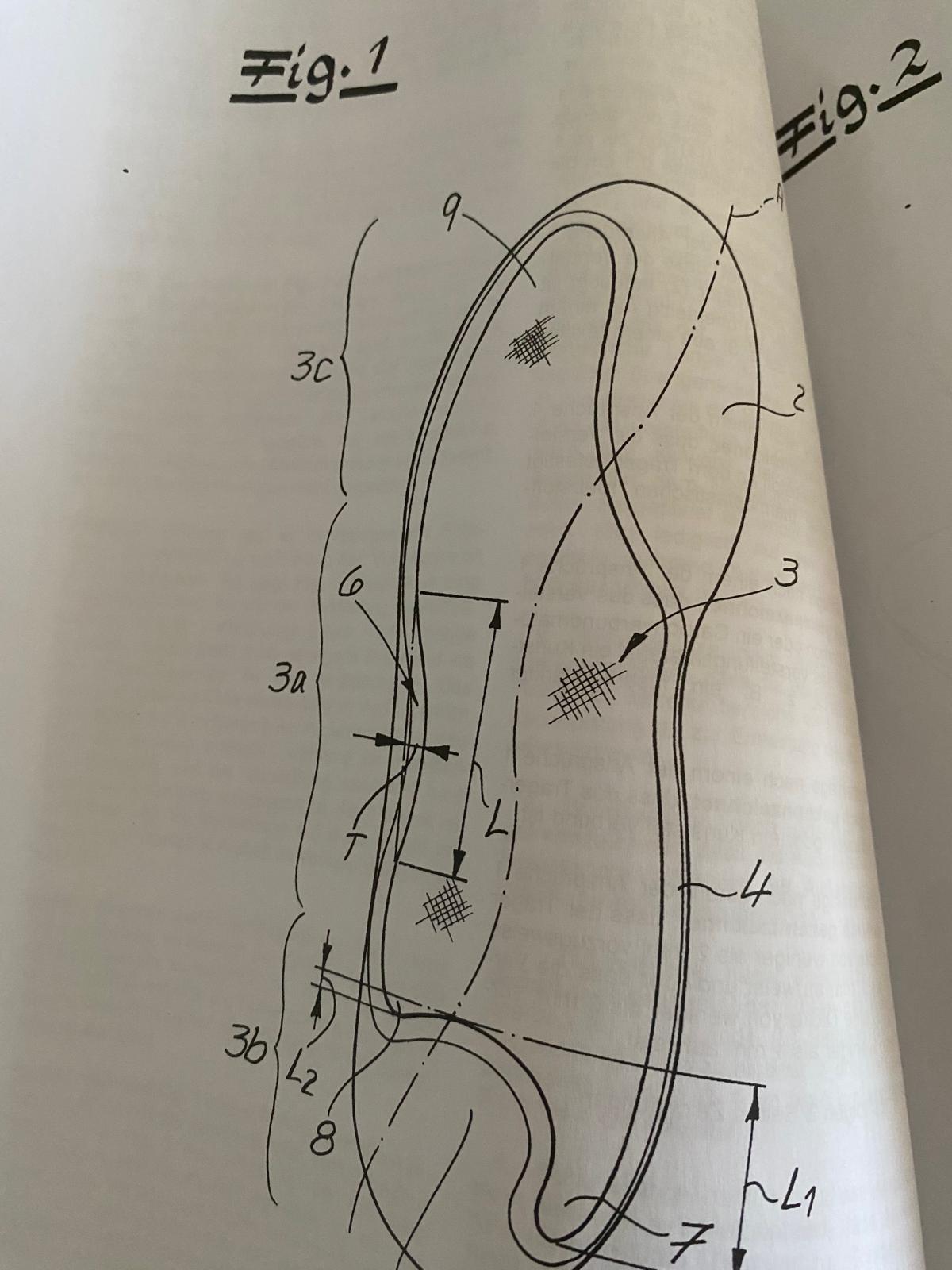
Fig. 1 – Top view with complete stiffening contour
What does the drawing show?
Fig. 1 shows the shoe insert (1) from above: the sole-shaped carrier (2) with its outline (4) and the smaller stiffening (3) inside it, across all three zones: forefoot (3c), midfoot (3a) and rearfoot (3b).
Components shown
- 2Sole-shaped carrier
- 3 / 4Stiffening inside the carrier outline
- 3a / 3b / 3cMidfoot, rearfoot and forefoot area of the stiffening
- 7 / 8 / 9Medial and lateral clasp legs with heel recess
- L1 / L2Different lengths of the two clasp legs
Why constructed this way?
The drawing makes visible how the construction differs from prior art: the stiffening is smaller than the carrier, opened in a clasp shape at the rearfoot and guided as a narrow tongue on the lateral side only in the forefoot.
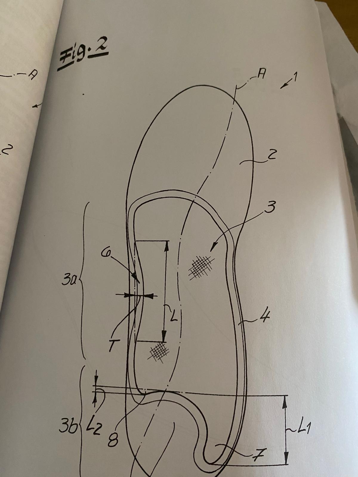
Fig. 2 – Top view with dimensioning of midfoot and rearfoot
What does the drawing show?
Fig. 2 also shows the insert in top view, focusing on the midfoot area (3a) and rearfoot area (3b). Axis A and the dimensions L, L1, L2 and T are indicated.
Components shown
- 3aMidfoot area of the stiffening
- 3bRearfoot area of the stiffening
- 7 / 8Medial (7) and lateral (8) clasp leg
- L1 / L2Lengths of the clasp legs along the longitudinal direction of the sole
- A / L / TAxis and further dimension indications entered in the drawing
Why constructed this way?
The dimensioning documents the characterising feature of the main claim: L1 (medial) is greater than L2 (lateral). The asymmetry is therefore not incidental but defined by construction.
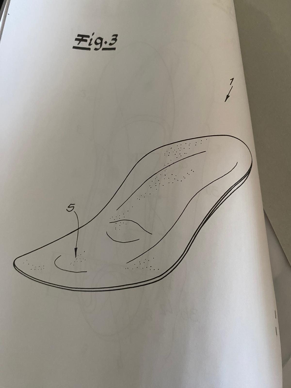
Fig. 3 – Perspective view of the insert
What does the drawing show?
Fig. 3 shows the shoe insert (1) in perspective. The three-dimensional shaping of the carrier and the material thickness of the insert are visible.
Components shown
- 1Shoe insert in perspective view
- 5Area of the insert marked with an arrow in the drawing
Why constructed this way?
While Fig. 1 and Fig. 2 show the surface layout, Fig. 3 makes clear that this is not a flat sheet but a spatially shaped body.
These drawings are planned to become interactively explorable in future: click a reference sign, show the explanation.